A ball mill coupling is a core transmission component connecting the motor, reducer, and ball mill cylinder (or main shaft). Its primary functions are to transmit torque, compensate for installation errors (e.g., axial, radial, and angular displacements), and buffer impact loads, ensuring stable operation of the ball mill under heavy-load and low-speed conditions.
Ball mills operate in environments often accompanied by vibration, dust, and high temperatures, so couplings must meet the following requirements:
High strength: Capable of withstanding torque ranging from thousands to tens of thousands of N·m;
Wear and corrosion resistance: Adaptable to dusty and humid environments;
Buffering performance: Reducing rigid impacts between the motor and cylinder;
Easy maintenance: Convenient for installation, disassembly, and replacement of vulnerable parts.
Depending on the specifications (e.g., small laboratory ball mills, large mineral processing ball mills) and working conditions, common types include:
Elastic Pin Coupling
Structure: Composed of two half-couplings, elastic pins (rubber or nylon), and baffles.
Characteristics: Simple structure, low cost, capable of compensating for minor radial and angular displacements, with moderate buffering performance. Suitable for small and medium-sized ball mills.
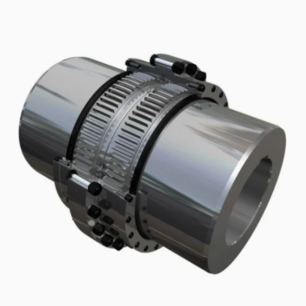
Gear Coupling
Structure: Consists of two half-couplings with external teeth and an outer sleeve with internal teeth. The tooth profile is usually involute, and grease lubrication is typically used.
Characteristics: High load-bearing capacity (torque up to 10⁶ N·m or more), capable of compensating for large radial, axial, and angular displacements. Suitable for large ball mills but requires high installation accuracy and regular lubrication.
Diaphragm Coupling
Structure: Connects two half-couplings via metal diaphragms (e.g., stainless steel) with bolts. Displacements are compensated through elastic deformation of the diaphragms.
Characteristics: No clearance, no need for lubrication, resistant to high and low temperatures. Suitable for occasions requiring high transmission accuracy (e.g., ceramic ball mills), but with higher cost and slightly lower load-bearing capacity than gear couplings.
Universal Coupling
Structure: Composed of two fork-shaped joints, a cross shaft, and bearings, capable of transmitting torque at large angles (≤35°).
Characteristics: Suitable for working conditions with large axis offsets, often used in auxiliary transmission systems of ball mills (e.g., feed inlet adjustment mechanisms).
Taking the gear coupling (the most widely used coupling in large ball mills) as an example, its manufacturing process is as follows:
Materials: Half-couplings and outer sleeves are typically made of high-strength alloy structural steel (e.g., 42CrMo, 35CrNiMo), requiring tensile strength ≥800MPa and impact toughness ≥60J/cm². Gear tooth surfaces can use 20CrMnTi (carburized and quenched) to improve wear resistance.
Pretreatment:
Raw material inspection: Spectral analysis (to ensure qualified composition) and flaw detection (ultrasonic testing for internal cracks);
Forging: Heating the steel billet (1100-1200℃) and forging (open die forging or die forging) to eliminate internal porosity and refine grains;
Annealing/normalizing: Annealing after forging (650-700℃ for 4-6h, slow cooling) to reduce hardness (≤250HBW) for subsequent processing.
Rough machining:
Turning: Turning the outer circle, inner hole, and end face on a lathe, leaving a machining allowance of 2-5mm;
Drilling: Drilling bolt holes (for connecting diaphragms or gears) with a 1-2mm allowance.
Heat treatment:
Quenching and tempering: 42CrMo and similar materials undergo quenching (850-880℃ oil quenching) + high-temperature tempering (550-600℃) to achieve a hardness of 280-320HBW, ensuring matrix strength;
Tooth surface strengthening (for gear couplings): 20CrMnTi external teeth undergo carburizing (900-930℃, carburized layer depth 1.5-3mm) + quenching (850℃ oil quenching) + low-temperature tempering (180-200℃), resulting in a tooth surface hardness of 58-62HRC and core hardness of 25-35HRC.
Turning: Precision turning of the journal, end face, and matching hole of the half-coupling to ensure dimensional accuracy (e.g., journal tolerance IT7-IT8, surface roughness Ra≤1.6μm);
Tooth profile machining:
Hobbing: Rough machining of the tooth profile to ensure pitch accuracy (GB 10095 Grade 7);
Shaving/honing: Finish machining of the tooth surface to reduce surface roughness (Ra≤0.8μm);
For carburized materials such as 20CrMnTi, gear grinding is required after carburizing to correct heat treatment deformation, ensuring tooth profile accuracy (GB 10095 Grade 6);
Drilling and tapping: Machining connecting bolt holes (e.g., M20-M48) with thread accuracy reaching 6H.
Non-tooth surfaces: After sandblasting for rust removal, apply primer (e.g., epoxy zinc-rich paint) and topcoat (e.g., polyurethane paint) with a total thickness ≥80μm to improve corrosion resistance;
Inner tooth sleeves of gear couplings: Apply anti-rust grease (e.g., lithium-based grease) to the inner tooth surface and install seals (e.g., O-rings) to prevent grease leakage.
For gear couplings: Connect the two external tooth half-couplings to the motor shaft and reducer shaft (or cylinder main shaft) via key connections (flat keys or splines), ensuring a fitting clearance of H7/k6;
Fit the internal tooth outer sleeve, check the tooth backlash (0.1-0.3mm), and install grease nipples;
Bei elastischen Kupplungen: Bauen Sie elastische Stifte mit einer Übergangspassung (H7/m6) zwischen Stiften und Bohrungen ein, um ein Lösen zu verhindern.
Die Inspektion umfasst Rohstoffe, Verarbeitung und Fertigprodukte, um den Designstandards (z. B. GB/T 4323) zu entsprechen. Elastische Hülsenbolzenkupplungen, GB/T 5014 Elastische Bolzenkupplungen, JB/T 8854.3 Zahnkupplungen).
Analyse der chemischen Zusammensetzung: Verwenden Sie ein direkt ablesbares Spektrometer, um Elemente wie C, Si, Mn, Cr und Mo zu erkennen, die den Materialstandards entsprechen (z. B. erfordert 42CrMo C: 0,38–0,45 %, Cr: 0,90–1,20 %).
Prüfung mechanischer Eigenschaften: Zugprüfung (für Zugfestigkeit und Streckgrenze), Schlagprüfung (-20 °C Schlagenergie ≥ 40 J) und Härteprüfung (≤ 250 HBW nach dem Glühen);
Fehlererkennung: Ultraschallprüfung von Schmiedestücken (GB/T 6402), um sicherzustellen, dass keine inneren Defekte ≥φ3 mm vorhanden sind; Magnetpulverprüfung (GB/T 15822), um auf Oberflächenrisse zu prüfen.
Maßhaltigkeitsprüfung:
Zapfen- und Innenlochdurchmesser: Gemessen mit einem Mikrometer oder einer Innenmessuhr, mit Toleranzen gemäß IT7-IT8;
Rechtwinkligkeit der Stirnfläche: Gemessen mit einer Messuhr auf einem Drehtisch, mit einem Fehler ≤0,02 mm/100 mm;
Zahnprofilprüfung:
Verwenden Sie einen Zahnradrundlaufprüfer, um den Rundlauf des Zahnkranzes (≤ 0,05 mm) und den Stirnflächenrundlauf (≤ 0,04 mm) zu messen.
Verwenden Sie ein Zahnradmesszentrum, um kumulative Teilungsfehler (≤ 0,1 mm/100 mm) und Zahnprofilfehler (≤ 0,015 mm) zu erkennen.
Oberflächenrauheit: Gemessen mit einem Profilometer, mit Nicht-Paaroberflächen Ra≤12,5μm, Paaroberflächen Ra≤3,2μm und Zahnoberflächen Ra≤0,8μm.
Härteprüfung: Verwenden Sie einen Rockwell-Härteprüfer, um die Härte der Zahnoberfläche zu messen (aufgekohlte Schicht von Zahnkupplungen ≥58HRC, Kern 25-35HRC);
Tiefe der aufgekohlten Schicht: Mit einem metallografischen Mikroskop beobachtet, um eine effektive Einsatztiefe sicherzustellen (1,5–3 mm);
Metallografische Struktur: Martensitgrad der Zahnoberfläche prüfen (≤Grad 3), Netzwerkkarbide sind nicht zulässig.
Montagemaßprüfung:
Gesamtlänge der Kupplung: Gemessen mit einem Stahlband, mit einem Fehler ≤±1 mm;
Koaxialität der beiden Wellen: Nach der Montage mit einer Messuhr den Rundlauffehler (≤0,1mm/m) und die Axialbewegung (≤0,2mm) prüfen;
Dynamische Unwuchtprüfung: Führen Sie für Kupplungen mit einer Drehzahl ≥ 1000 U/min dynamische Unwuchtprüfungen (GB/T 9239) mit einer Unwucht ≤ 50 g · mm/kg durch;
Belastungsprüfung: Führen Sie bei großen Zahnkupplungen statische Drehmomentprüfungen durch (Belastung mit dem 1,5-fachen des Nenndrehmoments, Halten für 10 Minuten ohne plastische Verformung);
Dichtungsleistung: Führen Sie bei Zahnkupplungen nach der Fetteinspritzung Drucktests (0,2 MPa) durch, ohne dass innerhalb von 30 Minuten eine Leckage auftritt.
Jeder Produktcharge muss ein Inspektionsbericht beiliegen, der Folgendes enthält:
Zertifizierung der Rohstoffe und Berichte zur Fehlererkennung;
Aufzeichnungen der wichtigsten Maßmessungen und Berichte zur Zahnprofilprüfung;
Berichte über die Härte der Wärmebehandlung und die Tiefe der aufgekohlten Schicht;
Ergebnisse der dynamischen Auswucht- und statischen Drehmomenttests des fertigen Produkts.
Strenge Herstellungsprozesse und Prüfverfahren gewährleisten die Zuverlässigkeit und Lebensdauer der Kugelmühlenkupplungen und erfüllen die Anforderungen eines langfristigen Schwerlastbetriebs von Kugelmühlen.